Sniffing SPI data from my Current Cost EnviR
I’ve successfully sniffed SPI data from my Current Cost EnviR (firmware v 1.29) using a Bus Pirate.
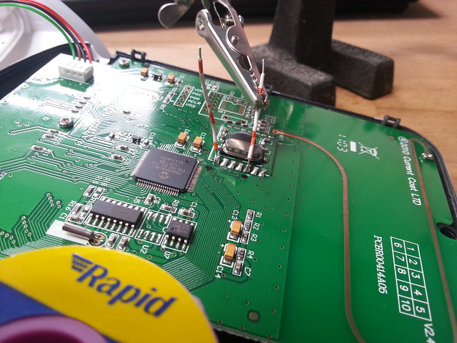
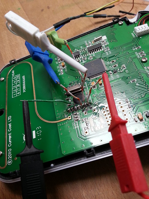
Here’s the back of the EnviR PCB. I soldered some wires onto the RFM01 module to make it a little easier to sniff data from the device:
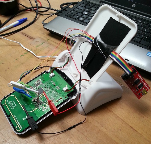
The Bus Pirate is wonderfully easy to use. Just connect it up to the
EnviR. Once the Bus Pirate is connected to a laptop, you can start
talking to it using screen /dev/ttyUSB0 115200. Put the Bus Pirate into SPI mode and then
start sniffing by typing (1). Easy peasy. Below are the results from some
SPI bus sniffing…
RFM01 configuration commands
Here are the commands the EnviR sends to its RFM01 module when it first starts:
 1 [892D
 2  E196
 3  CC0E
 4  C69F
 5  C46A
 6  C88A
 7  C080]

 8 [CE8B
 9  C081
10  C200
11  A618
12  CE89
13  CE8B]
This sequence of commands is very similar (but not identical) to the command sequence observed by gangliontwitch. My CC unit probably has a different firmware.
And here’s my attempt to interpret those commands using the RFM01 programming manual:
From RFM01 command #1 0x892D (gangliontwitch observed 0x892C)
eb=0 (disable low batt detection)
et=0 (disable wake-up timer)
ex=1 (enable crystal oscillator)
baseband bandwidth = 67kHz
dc=1 (disable signal output of CLK pin)

RFM01 command #2 E196 (5. wake-up timer command)

RFM01 command #3 CC0E (6. low duty-cycle command)
en = 0: disable low duty cycle mode

From RFM01 command #4 C69F (8. AFC Command)
a1 a0 rl1 rl0 st fi oe en
 1  0   0   1  1  1  1  1
a  = AFC auto-mode: keep offset when VDI hi
rl = range limit: +15/-16 (433band: 2.5kHz)
st=1 st goes hi will store offset into output register
fi=1 Enable AFC hi accuracy mode
oe=1 Enable AFC output register
en=1 Enable AFC function

From RFM01 command #5 C46A (9. data filter command)
al ml 1 s1 s0 f2 f1 f0
 0  1 1  0  1  0  1  0
al=0: disable clock recovery auto-lock
ml=1: enable clock recovery fast mode
s: data filter=digital filter
f: DQD threshold = 2

From RFM command #6 C88A
3918.5 bps

From RFM01 command #7 C080 (4. receiver setting command)
d1 d0 g1 g0 r2 r1 r0 en
 1  0  0  0  0  0  0  0
d: VDI source = clock recovery lock output
g: LNA gain = 0 dBm
r: DRSSI threshold = -103 dBm
en=0: disable receiver

GanglionTwitch has command CE88 here, my CC doesn't (11. output and FIFO mode)

From RFM01 command #8 CE8B (11. output and FIFO mode)
f3 f2 f1 f0 s1 s0 ff fe
 1  0  0  0  1  0  1  1
f: FIFO interrupt level = 8
s: FIFO fill start condition = reserved
ff=1: enable FIFO fill
fe=1: enable FIFO function

From RFM01 command #9 C081 (4. receiver setting command)
d1 d0 g1 g0 r2 r1 r0 en
 1  0  0  0  0  0  0  1
d: VDI source = clock recovery lock output
g: LNA gain = 0 dBm
r: DRSSI threshold = -103 dBm
en=1: enable receiver <--- only diff from command #7

From RFM01 command #10 C200 (7. Low Batt Detector & MCU Clock Div)
d2 d1 d0 t4 t3 t2 t1 t0
 0  0  0  0  0  0  0  0
d: frequency of CLK pin = 1MHz
t: low batt detection theshold = 2.2+0 V

From RFM01 command #11 A618 (3. frequency setting command)
Fc = 433.9MHz

From RFM01 command #12 CE89 (11. output and FIFO mode) (gangliontwitch has CE88)
f3 f2 f1 f0 s1 s0 ff fe
 1  0  0  0  1  0  0  1
f: FIFO interrupt level = 8
s: FIFO fill start condition = reserved
ff=0: disable FIFO fill
fe=1: enable FIFO function

From RFM01 command #14 CE8B (11. output and FIFO mode)
f3 f2 f1 f0 s1 s0 ff fe
 1  0  0  0  1  0  1  1
f: FIFO interrupt level = 8
s: FIFO fill start condition = reserved
ff=1: enable FIFO fill
fe=1: enable FIFO function
Data from Current Cost sensors
This is raw data from the SPI bus; it hasn’t been demanchesterised. My tinkering is consistent with gangliontwitch’s description of what each byte is used for.
16 bytes from IAM (180W, ID=3455):
 0 55 <--- button pressed indicator?
 1 A6 <--\
 2 6A <---}-- radio ID?
 3 AA <--/
 4 95
 5 55
 6 9A <--- watts MSB?
 7 65 <--- watts LSB?
 8 55
 9 55
10 55
11 55
12 55
13 55
14 55
15 55

16 bytes from IAM (0 watts, ID=3455):
 0 55
 1 A6
 2 6A
 3 AA
 4 95
 5 55
 6 55
 7 55
 8 55
 9 55
10 55
11 55
12 55
13 55
14 55
15 55


16 bytes from a different IAM (0 watts, ID=3913):
 0 55
 1 AA <--\
 2 65 <--+-- ID?
 3 96 <--/
 4 95
 5 55
 6 55
 7 55
 8 55
 9 55
10 55
11 55
12 55
13 55
14 55
15 55

From IAM after button has been pressed:
 0 95 <-- button pressed indicator?
 1 96
 2 6A
 3 96
 4 95
 5 55
 6 55
 7 55
 8 55
 9 55
10 55
11 55
12 55
13 55
14 55
15 55

From CT clamp (0 watts, ID=77)
 0 55
 1 55
 2 65
 3 A6
 4 95
 5 55
 6 55
 7 55
 8 55
 9 55
10 55
11 55
12 55
13 55
14 55
15 55