Insulating our Victorian living room
A quick health warning: the blog below makes it sound like it’s a huge amount of effort to insulate a Victorian property. And it was a huge amount of work to do our living room! But I’d say that 90% of the work we had to do was correcting mistakes made by previous owners / the original builders. If we had started with a healthy Victorian house then it would have taken a fraction of the time. OK. Are you sitting comfortably? Let’s start the story…
We have a draughty, poorly insulated Victorian end-of-terrace house. Back in January 2009, the weather was freezing and work was quiet so I decided to take the plunge and insulate our living room.
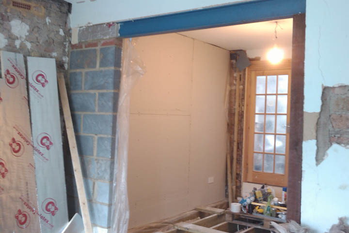
Here’s what the living room looked like before I got stuck in:

Not only did I want to reduce our gas consumption but the room was also decidedly uncomfortable on cold winter days: even if we left the heating on all day, the living room would still be uncomfortably chilly.
The original plan: On the floor, I planned to pull up the floor boards, install chicken wire under the joists, lay glass fibre insulation between the joists and re-lay the floor boards. On the external walls, I intended to glue 60mmKingspan K17 insulated dry lining board directly to the walls. Before starting the project, I expected it to take a month (i.e. January 2009). At the time of writing (July 2010) the project still isn’t finished, largely because the room provided plenty of surprises once we started revealing the underlying structure.
And here’s what it looks like after 18 months of work!

What exactly did I hope to achieve by insulating? The aim was to reduce the rate at which the external walls lose heat by a factor of 7 (to explain where that factor of 7 comes from: 9” solid brick walls have an uninsulated U-value of 2.1 watts per square meter per Kelvin (W/(m²⋅K), whilst 9” brick plus 70mm of polyurethane foam insulation has a U-value of 0.3 W/(m²⋅K)) and to reduce the rate at which the floor loses heat by a similar factor. Achieving a wall U-value of 0.3 W/(m²⋅K) puts us firmly in the territory of the Energy Saving Trust’s “recommended specs” and means that we exceed the building regs for both 2006 and 2010 (but, to put this in perspective, a Passivhaus / Code 6 would have wall U-values around 0.15 W/(m²⋅K))
Starting the project: pulling up the floor boards


After pulling up just a few boards, it was clear that something was wrong. Suspended timber floors are supposed to be just that: suspended! Our joists were just resting directly onto the damp ground. They are supposed to be raised off the ground so that air can circulate under the joists to reduce the probability of the joists rotting, like this:

In the photo above, you can see a seriously rotten joist. This joist was resting directly on the damp ground (the photo shows it suspended because we dug a hole to test how deep our steppings go: about 450mm below floor level, if I remember correctly).
It’s highly likely that much of the rubble in the floor void came from when a previous owner removed the chimneys and dividing wall.


So, after spending a few days pulling up the floor boards, the project had already grown considerably: we now knew we had to completely rip up the joists, dig down and install new joists. Oh joy. But the room had plenty more surprises in store for us:
The walls: damp & broken

In the photo above, you can (just about) see a large damp patch on the lower right of the wall. Even stranger, you can also see a horizontal streak of damp on the top left of the photo. We originally thought that perhaps this horizontal streak was caused by a leaking pipe but no pipes run anywhere near the streak.
We invited 3 damp experts to give their advice. They came along and stuck their damp meters into the wall. We got three different replies. One guy said the damp wall is just condensation and nothing to worry about. The other guy said we need to strip the wall back to the bare brick, inject a chemical damp proof course and then re-plaster with waterproof concrete.
I decided to investigate a bit more on my own…
I was very curious about the horizontal streak so I chiselled away the plaster to investigate:


Clearly the wall wasn’t happy. By this stage, it was clear the wall had a serious damp problem and that some of the brickwork was a bit crumbly. After a lot of research, I started trying to piece together what was going on. The previous owners had clearly already attempted to remedy the damp by injecting a chemical damp proof course at floor level and by plastering with a waterproof cement. The weird horizontal damp streak I had seen was a crack in the waterproof cement allowing water from the damp brick onto the plaster. The problem with applying waterproof concrete is that, at best, it just temporarily fixes the symptoms (by preventing damp getting to the internal wall surface) rather than fixing the problem. The real problem with applying a concrete render is that the brickwork behind the concrete is actually made more damp because water can’t evaporate off the internal surface; plus these old houses are built with lime mortar which moves a little during the seasons but concrete has no “flex” to it, hence either the brickwork or the concrete (or both) crack as the brickwork tries to move against the rigid concrete. Damp walls are a real concern for two main reasons: 1) any timber in the wall will rot and 2) damp is not good news for the structural stability of bricks and mortar.
I did everything I could to ensure that the wall wasn’t taking on water from any broken guttering or anything like that.
I decided that I just had to bite the bullet and go for the solution which would take bloody ages but would result in a healthy wall plus a dry internal finish: strip the walls back to the brick (to allow them to breath) and then install the insulation in timber stud walls supported 30mm away from the brick and ventilate this 30mm cavity to the outside. The end result would be that the walls will be able to breath (and hence shouldn’t accumulate too much water content).


So I stripped the wall with a hired mechanical chisel (not a fun job). Some of the brickwork was not particularly happy so I ordered a bunch of lime putty from Mike Wye Associates and repaired the dodgy patches of wall by carefully removing a brick at a time and replacing with a new brick and lime mortar. Later I also added an additional 9 air bricks to the external wall (there was only 1 air brick installed originally) to satisfy building regs.


Next problem: the internal load bearing walls need underpinning!
OK. Fine. So we had to remove the existing floor joists and dig down to install a new floor. But wait! We can’t dig down because it turns out that the internal, load bearing walls are just built onto the ground floor floor boards and then building rubble has been wedged underneath to help take the load. And we always wondered why the floor boards were so deflected!


The section of wall in the photo above is taking a huge weight. Not only is it supporting the 1st floor joists but it’s also taking some of the load from the roof.
So we decided to get a structural engineer to come and take a look. He recommended that we underpin the internal walls so we shopped around for a builder. The job took a week and didn’t cause too much disruption. The job was signed off by the local building control officer.
Next: install floor joists
So we dug down enough to mean that once we installed our new, 200mm deep joists, there would be an air gap of at least 150mm between the bottom of the joists and the ground. It’s a good way to get fit! We were very lucky to have some help from some friends. In total we removed over 7 tonnes of earth.


Our structural engineer also drew up plans for our new floor (although it’s not strictly necessary to get an engineer to do this, there are standard tables from TRADA for specifying the size of the joists you need for a given free span). We used 200x50mm C16 joists and we ensured that there was at least a 150mm gap between the bottom of the joists and the ground. We could have used shallower joists if we’d installed more sleeper walls but that probably would have been more work and would have required more concrete (and around 1kg of CO₂ is released during the production of each kg of cement).
The 50x200mm joists cost about £270 including delivery.
At the centre of the room, the joists rested on a sleeper wall built off a foundation installed when the underpinning was done.
Where the joists met the wall, the joists were usually supported by joist hangers which I installed in the wall. Where this wasn’t possible, I built new strip foundations and sleeper walls (the structure was, from ground up: 450mm deep (measured from top of clay) strip foundation, honey comb wall, mortar, DPC, mortar, 50x100mm timber, joist).


I had to re-do several of the joists to get it all level. Getting a floor level in every direction is surprisingly tricky, especially when the joists vary in thickness by as much as 3mm (yes, I let the joists acclimatise for over a month)

Insulating the external wall
The plan for insulating the wall was to:
- Wedge as much insulation as possible into the void between the ceiling and the first floor.
- Build a timber stud wall using 50x50mm studs at 600mm centres, leaving a 30mm ventilated cavity between the brick and the back of the stud wall. Ventilate this cavity to the outside by adding air bricks in the wall.
- Secure the studs at floor and ceiling and twice along the length (because 50x50mm studs are not strong enough to span from ceiling to floor without bending). Ensure that moisture can’t pass from the brick into the wood.
- Put 50mm Celotex between the studs and a further 30mm over the studs to limit cold bridging. Total insulation thickness = 80mm and a U-value of 0.29 W/(m²⋅K). Fill gaps with expandable foam. Tape over the joints.
- Put a vapour control layer over the insulation
- Pay attention to where the VCL meets the corners, ceiling and floor. Warm, moist air from the living space must not be allowed to escape into the cavity behind the insulation (if it does then the water vapour will condense and the liquid water will make the wood attractive to fungi and/or bugs). It’s also important to ensure that cold air from the cavity can’t get into the gap between the ceiling and the first floor.
- It’s also important to make sure that cold air can’t enter the gap between the different layers. So I spent a lot of time gluing / injecting expandable foam into these gaps.
- Wherever possible, I offset the plasterboard relative to the insulation sheets such that each plasterboard always spanned at least one joint in the insulation. This helps make the end product as flat as possible and helps with airtightness.
- The wall insulation extends below floor level and above ceiling level and the wall’s vapour control layer is overlapped and taped to the floor’s VCL and to the plasterboard ceiling.
This strategy quickly turned out to be extremely time consuming. If I were to do it again I definitely would use thicker studs and not worry so much about the cold bridging effect of the wood (for a given width, wood conducts heat 20 times faster than the Celotex). So, if I were to do it again, I’d go for something like 50x80mm studs with 80mm of insulation between the studs and just put the plasterboard directly onto the studs.

Insulation and plasterboard delivered from Planet Insulation. The 50mm sheets of insulation (1200x2400mm) were £13.50. Our total order was:
insulation buying from planetinsulation:
- 10 x 50mm ga3000 between studs
- 10 x 30mm tb3000 over studs
- 10 x plasterboard
- jointing tape
- £360.14 including delivery

The first few studs are going in. You can see one of the attachment points between the strut and the brick, using DPC to protect the wood from the damp wall and plastic shims to get the stud straight. The short bits of wood running at right angles behind the studs are to stop the insulation from entering the cavity.


Here you can clearly see the void between the stud wall and the brick:


I seriously considered pulling the entire ceiling down to insulate the ceiling fully. I didn’t do that because I was advised that pulling ceilings down is an absolutely horrible job (very dusty) and because I intend to insulate the upstairs rooms eventually (i.e. my ultimate goal is to install a continuous layer of insulation surrounding the entire building envelope).
What I did do is I cut away about 100mm of the ceiling like this:

…and I pushed as much glass wool insulation as would fit into the void between the ceiling and the first floor. So the edge of the ceiling shouldn’t bridge to the cold external wall.
My original plan was to continue the 80mm layer of Celotex up past the ceiling, all the way to the first floor floorboards (I knew the 1st floor joists run parallel to the external wall). That wasn’t possible because the wooden structure up there is really complex and messy (presumably something to do with chimneys and fireplaces). So I just wedged as much glass wool insulation up there as would fit (which wasn’t much fun because I got covered in glass fibre and the gunk in my nose turned to fibreglass! - I quickly learnt that a face mask is a very good idea when working with glass wool insulation).
Starting to tape up the gaps between the first layer of insulation:


Laying the vapour control layer over the insulation (yes, Celotex has an integral VCL but I wanted to make sure the construction is as airtight as possible):


Gaps taped, VCL installed, the first sheet of plasterboard in place and I’m fixing the first mains socket in place (building regs allow mere mortals like us to extend existing mains rings).


Taping from the top of the wall’s VCL onto the ceiling:


The first coat of dry-wall mud:

I found that the back door had been installed by muppets - it actually wasn’t secured to the brick at all. So I had to make sure the door frame was secured into the brick.


The previous owners knocked out the internal wall which separated the dining room and the front room to make a single, large front room. The structural engineer had identified that the beam the previous owners had installed was no where near strong enough (it was visibly deflecting and the wall above the beam was cracking). So he specified a reinforce steel joist to go under the existing wooden beam which I ordered and installed with help from Ginnie. I tried using a car jack from my wife’s car to ensure the RSJ was forced firmly against the existing wood. I assured my wife that “of course I wouldn’t break the jack”. My RSJ-lifting-car-jack worked well for a bit and I was feeling pretty smug. Until it let out an almighty crack and the car jack was no more. Anyone know where I can get a replacement Ford Focus car jack?!


I also made sure to insulate the RSJ to prevent it from conducting heat into the cold brick wall. We specified the beam to not extend all the way into the wall as can be seen in this photo:

I then added 100mm of Celotex at the end of the RSJ. So, going from the 9” external brick wall to the beam, first you come across a 30mm cavity, then 100mm of Celotex and then the beam. I liberally applied expandable foam to make sure no cold draughts can travel up the beam.
So the beam shouldn’t be able to conduct heat directly to the cold external wall.
In the photo below, you can just about see the 100mm of Celotex at the end of the beam and the Celotex I put along the length of the beam:
I did the wall insulation in two stages. First I did the wall which would become our dining room and I took this up to the stage of the first layer of drywall mud before I even started the other half of the wall. This allowed me to change my strategy for the second half of the wall. Instead of using 50x50mm struts, I used 100x25mm struts tied securely to the brick and then put entire sheets (1200x2400mm) of insulation straight over the studs. This had the huge advantage that I didn’t have to spend time cutting the insulation. It did mean that, at places, the distance between the back of the studs and the brick would be less than 30mm but because the wall was so damn warped, most of the gaps between the brick and the back of the studs were over 30mm so air should move easily behind the studs.

One of the more frustrating aspects of building the wall was trying to create a straight end-product whilst starting with materials and surfaces which are bent, twisted and bulging. The brick wall definitely wasn’t straight and the wood was bent and twisted. It took a lot of careful measuring with a plumb line to get the wall straight. The plastic shims (in 1mm, 3mm, 5mm and 10mm sizes) were a god-send.


I also put a few 1-wire temperature sensors behind the insulation so I can monitor the performance of the insulation when it’s all up and running:

And a really bodgy moisture detector: (yeah, yeah, I know - the metal will corrode which will confound the readings. But I wasn’t gonna spend a hundred quid on platinum electrodes.)

And an even bodgier moisture detector (the idea is that any condensation on the wall will drip into the collecting pot which will be detected as a decrease in resistance). Hopefully there won’t be any condensation though!

Bliss:

Don’t tell my wife but in places we’ve lost 145mm of wall. To be honest, this was more a side-effect of making the finished wall straight whilst the brick bends outwards from the top to bottom.


Using expandable foam to prevent cold air from getting from the ventilated cavity into the space between the ceiling and first floor:

Using bits of wood to make sure the insulation glues level:


The cables run in the ventilated cavity and then where they penetrate the insulation I filled the hole with expandable foam. Using expandable foam to stop air getting through the gaps between the insulation and in the service holes:


So the cables do spend about 50mm of their length buried in insulation which is perhaps a little naughty but I’m hopeful they’ll not overheat because even if that 50mm stretch of cable becomes hot, that heat should conduct into the cable in the cold cavity. Perhaps I should have over-rated the cable which goes through the insulation.
I then put a ribbon of glue between the internal surface of the Celotex and the VCL, creating a rectangle of glue about 30mm outside the perimeter of the socket so that no draughts can get from the socket behind the rest of the plasterboard.
The housing for the sockets extends 30mm into the 80mm insulation so there’s still 50mm of insulation between the back of the sockets and the cold brick wall so hopefully the temperature at the back of the socket will remain well above the dew point.
Me. Drywalling:

After many hundreds of hours of use, the trigger on my battery drill stopped working so I hacked together a quick (but ugly) fix:


Next I insulated the roof of our single-story bay window:

You can’t see it very well in this photo but the end result is that the bay ceiling is now filled with glass fibre insulation (I left a bit of a gap at the top for air flow) and covered in a vapour control layer:

And we also installed a mechanical ventilation unit with heat recovery:
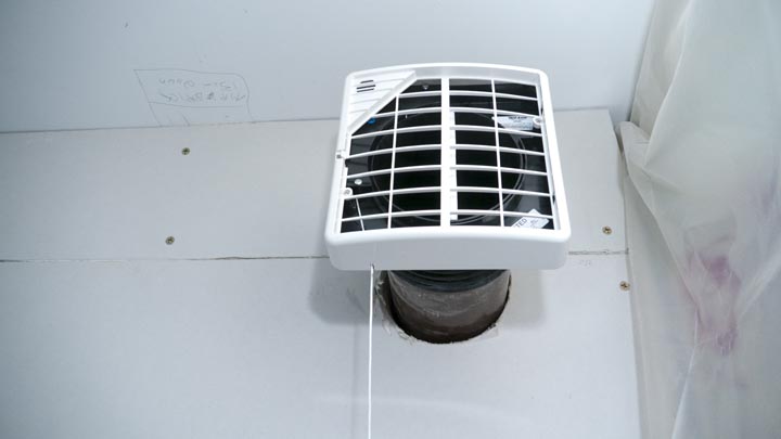
I’m trying to make the room as air-tight as possible to minimise heat loss so I wanted to install MVHR to prevent the room from getting too stuffy. The unit sucks warm air out of the room and pulls fresh air into the room. It transfers 85% of the heat from the warm exhaust over to the clean incoming air. So you get fresh air without wasting too much heat. It uses 2 watts of electrical power (which is a quarter of the power our broadband modem uses). You can read more about my MVHR installation on a previous blog entry.
Insulating the floor
Each roll was about £12 from B&Q (they were doing these rolls for £5 a pop a few months ago but no more)

But first, some more 1-wire temperature sensors on the flow and return pipes of the radiator so I can get some way towards estimating the rate at which heat flows into the room (to calculate the energy emitted by the radiator you need to know temperature drop across the radiator and the flow rate; I can measure the temp drop but I’ll have to estimate flow rate).


And a temperature sensor on the mains water pipe. Just because I can (or rather: so I can test the “old wives tale” that you have to set your heating to trigger daily over winter even when you’re away so the pipes don’t freeze; I don’t think the pipes will get anywhere near zero even when the external air temp goes well below zero)

Here you can see the heringbone strutting I’ve added to the ends of the joists. It’s amazing how much sturdier the joists feel after adding strutting at the centres and ends of the joists. My trigonometry got a bit of an exercise calculating the angles for the ends of the strutting.


Close up of the chicken wire installed under the joists to hold the insulation in place:

Two essential tools for the DIYer: a work bench and a laptop running iPlayer!


I have to ensure that air can flow from under the joists to the cavity behind the walls:


Showing the >150mm under-floor air cavity. The black 25mm MDPE pipe (£12 for 25m) snaking across the bottom will take rainwater from our yet-to-be-constructed wooden 1500 litre water tank in the back garden to a garden tap in the front garden)

More sensors (here you can see the sensors for floor temp, under-joist temp and the temperature 300mm below ground)

Trying to figure out which new floor finish we like:

Getting there:
The local building control officer signed off on this project a few days ago.
Why didn’t we insulate externally?
It’s usually assumed to be better to insulate solid-walled properties externally (i.e. stick the insulation on the outside) rather than internally. Why didn’t we insulate externally? There were several reasons:
- The gap between our house and our neighbour’s house is only
about 680mm. If we added 150mm of insulation+render then the gap
would become too small to get walk though / get a wheel barrow down.
The gap is used by our neighbour to access her back garden.

- We approached several external wall insulation companies and they all said they wouldn’t be able to put up their scaffolding in such a narrow space
- We only use the room for about an hour an evening so you could actually view the low thermal mass as a benefit because it’ll warm up quickly on demand.
- I am considering externally insulating elsewhere on the house including, rather bizzarely, the bedroom above the living room. The folks on the Green Building Forum provided some excellent advice on insulating the bedroom externally despite the downstairs being insulated internally.
Why didn’t we install a solid concrete (or hempcrete) floor?
Because:
- the walls suffer from damp. Several people told me that installing a solid floor reduces the rate at which moisture evaporates from the soil and hence increases the rate at which moisture travels into the walls
- the suspended timber floor in the hall way is already poorly ventilated. Installing a solid floor in the living room would basically completely cut off any ventilation to the hall way’s floor
- ALL our mains services (water, power, gas, sewage) travel under the living room floor and I’m reluctant to bury those services under concrete
- We’d use multiple tonnes of concrete (which isn’t great for our CO₂ footprint)
None of these issues are impossible to overcome so we could have installed a solid floor if we really, really wanted to. But, all things considered, a suspended timber floor seemed the way to go.
I thought you were trying to be environmentally friendly? Polyisocyanurate (PIR) insulation isn’t a very “green” product, is it?
PIR is derived from a petrochemical feedstock.
My general attitude to fossil oil is that it isn’t intrinsically “bad”. The main reason why oil is considered environmentally damaging is because it produces CO₂ when burnt, and large quantities of CO₂ change our environment in ways in which humans and many other species are not optimised for. But fossil oil can be used as a chemical feedstock for a vast variety of products from pharmaceuticals to plastics without producing CO₂. Yes, you certainly can point to countries where oil production has led to serious geopolitical problems and it’s also true that oil drilling is one of the deadliest jobs in the western world; although it may be more accurate to say that mining of any mineral resource (not just oil) is dangerous to life and political stability. But at the moment, fossil oil is one of the only options we have for producing PIR insulation at scale. Maybe we’ll be able to use plant oils instead but then you have to worry about competing with growing space. There’s no obviously right answer. Barring the utility-scale roll-out of nuclear Fusion within the next decade (which ain’t gonna happen), we absolutely have to reduce energy consumption in our buildings and insulating with PIR is an excellent way to insulate. Put it this way: I’m far more comfortably using oil as a material than burning it inefficiently in internal combustion engines (although I still do that when I have to).
A quick rant: one of my biggest bugbears about the environmental movement is a general attitude that “natural” products are intrinsically “better” than “man-made” products. Firstly, the distinction between “natural” and “unnatural” is, in my humble opinion, entirely arbitrary. Why is a straw bale considered “natural” whilst a nuclear fission reactor is considered “unnatural”? The cereal crop was sown, irrigated, cut, dried and packaged by humans, largely using diesel-hungry tractors. Why is refining straw fundamentally different to refining uranium? The physical world doesn’t differentiate between “man-made” things and “natural” things; they all obey the same physical laws and principals. We are part of nature. We cannot help but be part of nature. Everything we do is “of nature”, whether it’s digging an irrigation trench or building mobile telephones or flying in machines made of aluminium and steel. All of these things exist within the natural world. It’s all “natural”. I see no fundamental difference between a bird using twigs to create a nest and a human using polyisocyanurate to insulate their house. Indeed, I believe one of the most damaging and arrogant memes is the idea that we humans are fundamentally “above” the rest of nature. The main difference between us and other animals (in the context of environmentalism) is that we have the ability to observe the changes we are making to the environment and predict that those changes will, in some instances, cause real problems. Hence our responsibility is to use whichever products create the least disruptive changes to the environment over the entire life cycle of those products. Whether those products are “natural” or “man-made” is not just irrelevant, it’s not even a meaningful question in the context of engineering the “best” performing house.
Rant over.
The blowing agents (used to make the product into a foam) are greenhouse gasses and some damage the Ozone layer
True. But Celotex use blowing agents with a low global warming potential and zero Ozone depletion potential.
It uses energy & water to produce these insulation materials.
True. But the amount of energy used in production is miniscule compared to the amount of energy the product will save when it’s installed.
All products require energy to create them, including sheeps’ wool and other “deep green” products (although you could argue that “waste materials” like straw have a negligible footprint.)
Foam insulation products leak gas over their lifetimes.
True. And this causes two problems: 1) they leak gasses which may not be great if they’re inhaled and 2) the foam boards shrink a little bit over their lifetimes.
The gases will remain behind our vapour control layer and will be ventilated to the outside so we wont be inhaling these gasses.
I’ve made sure that even if the boards shrink a lot, they’ll stay in place and I’ve taped over the gaps between the boards and offset the gaps between the different layers so the construction should remain airtight even when the foam insulation has shrunk a bit.
Why didn’t you use a breathable insulation like wood fibre attached directly to the wall instead of using an impermeable product with a ventilated cavity?
Because:
- To get the same performance, we would have had to use even more thickness
- I’m not entirely happy with the idea that the moisture from the (quite seriously) damp wall will be allowed into the living space. We may have to run a dehumidifyer which guzzles power.
- I’m sceptical of claims that the wood fibre maintains its U-value even when damp (although I have no empirical evidence to substantiate this scepticism)
- We (and every subsequent owner of the house) would be restricted to using breathable wall finishes
The bottom line…
…is that, as far as I can tell, our insulation will repay its manufacturing footprint many times over by reducing the footprint of our house. No, Celotex isn’t perfect, and alternative products may perform better on specific criteria, but overall Celotex ticks more boxes for our specific project than any other material I considered.
So, um, how does it feel to do all this work?
On the one hand, I’m definitely glad that we took the plunge. The room should be a lot warmer, more comfortable and considerably prettier than when we started. But it has taken over 18 months and thousands of pounds.
For most of 2009, I tried to fit the DIY work in around my “real” work (filmmaking). This didn’t work at all because the filmmaking work just expands to fill any space it possibly can. So in 2010 I started turning away work to get the living room done ASAP (which makes financial sense because it would’ve cost well over £10,000 to get builders to do the work - which is more than I can earn in that period). This was fine for the first few weeks but started to get genuinely quite distressing after a while. Like everyone else, I have career ambitions and it’s really very troubling to feel like my life has been put on hold while I do this damn construction project. What really annoys me is that a good 90% of the work I’m doing is correcting other peoples’ mistakes. Grrrrrr…
Anyway. We’re almost there now. I’ve learnt a heck of a lot. But I’m not sure how useful this new found DIY knowledge will be in the future! I certainly have a huge amount of respect for (good) builders. Building is really, really, really hard work and takes ages. But the end result should be good: a seven-fold decrease in the rate at which the room loses heat and a much more comfortable and pretty room.
I really must emphasise that improving the thermal performance of a Victorian house really shouldn’t be as hard as it was for me. Like I said - most of the work we had to do was correcting structural problems rather than actually insulating. We were particularly unlucky in that pretty much everything that can go wrong with a Victorian property did go wrong. If we had started with a healthy, well maintained house then we could have insulated it within a month, working just at weekends. For example, see my friend Simon’s blog about insulating his healthy Victorian floor.
Tips
General
- This sounds obvious but it wasn’t to me: keep the design as simple as possible! Something you think will only add 10% labour will inevitably add 100%. I’m not saying you should compromise on quality or performance, just always go for the simplest option. Building is really, really hard work and seriously time consuming. Don’t make it any harder than it absolutely needs to be.
Lifting floor boards
- Using a crow bar to gently lever the boards up saves a lot of time
Installing foam insulation
- If you’re using expandable foam then make sure you wear gloves and goggles. Expandable foam takes ages to remove from your skin. And familiarise yourself with foam remover - if you don’t finish an entire bottle of foam then you can clean the nozzle with foam remover and use the bottle of foam later.
Free resources
- The Energy Saving Trust “Practical Refurbishment of Solid Walled Houses”contains a wealth of useful information. Highly recommended. Browse their other documents as well
- Read past posts and post your own eco-DIY questions on the excellent Green Building Forum
- For discussing green technology (and green DIY) you can’t beat the Navitron Forum.
- Ask general building / plumbing / electrical questions on the ScrewFix Forum
- Download the relevant Building Regs. No, it’s not thrilling reading. But it is important to comply with building regulations. I was sceptical of building regs before I started this project but I’m glad I decided to comply. And the thing that really gets me is that if the previous owners of the house had complied with building regs then they could’ve saved me a huge amount of work by getting the job done right the first time round.
- An amazing “zero energy” Victorian refurb including very high performance triple glazed sash, running underfloor heating pipes under the slate tiles to collect heat and a 300m^3^ solar store for storing heat from summer to use in winter.
- Programme your DVR / Sky+ / VCR to record all the repeats of Grand Designs. When your project is going badly, nothing helps you to gain some perspective better than seeing an even nastier building nightmare!
Even more photos on Flickr.
There’s some discussion of this blog posting on Navitron and on the Green Building Forum.
Update: I’ve finally written a follow-up post to this blog! Insulating our Victorian living room part 2