Current Cost Individual Appliance Monitor v3 tear down
UPDATE: DO NOT TAKE APART A CURRENT COST IAM UNLESS YOU REALLY KNOW WHAT YOU’RE DOING. IT APPEARS THAT THE CIRCUIT BOARD IS NOT ISOLATED FROM THE MAINS. HENCE SECTIONS OF THE PCB WHICH YOU MIGHT ASSUME ARE AT ONLY A FEW VOLTS MAY IN FACT BE HUNDREDS OF VOLTS ABOVE EARTH. I.E. ELECTROCUTION RISK! HOW DO I KNOW? BECAUSE I BLEW UP MY LAPTOP ATTEMPTING TO SNIFF SPI DATA FROM AN IAM!
What does a Current Cost Individual Appliance Monitor v3 look like inside? Let’s find out… (click on a photo to view it full-size on Flickr)

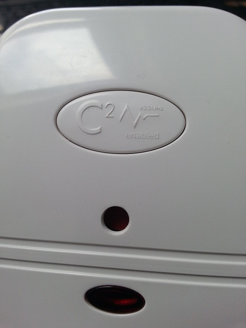
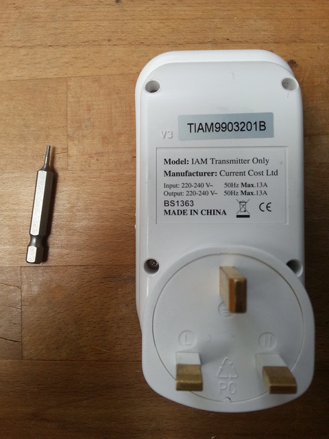
Note that this IAM claims to be a “transmitter only”. This is supposedly to differentiate it from the EDF Wireless Transmitter Plug which can send and receive data.
Disassembly
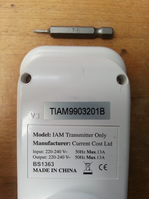
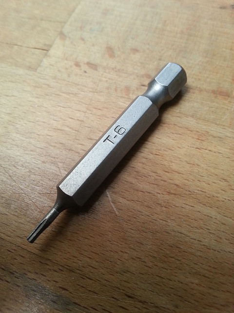
You’ll need a T6 torx screw driver to take the screws out. The best I could find at my local DIY store was this T6 torx bit. This was fine for the top 2 screws but couldn’t reach the lower 2 screws.
Inside
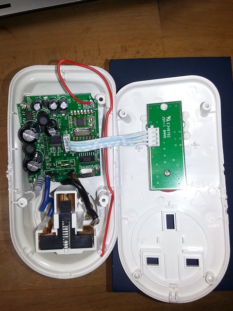
The red wire is the aerial.

The RF transmitter module (top of the photo, to the right of the red aerial wire) is very likely to be an RFM02 but I haven’t confirmed this by sniffing the SPI bus. The RF transmitter IC has “ST8886 1123AR FOGO” written on it. I haven’t found what this chip is, even after lots of googling.
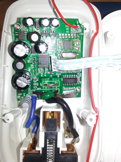
In the photo above you can just about see that the neutral mains pin passes straight through the IAM whilst the live connection goes through the PCB and through a very chunky jumper. Supposedly the IAM measures the voltage drop across the chunky jumper to measure current.
UPDATE: TO REPEAT: DO NOT TAKE APART A CURRENT COST IAM UNLESS YOU REALLY KNOW WHAT YOU’RE DOING. IT APPEARS THAT THE CIRCUIT BOARD IS NOT ISOLATED FROM THE MAINS. HENCE SECTIONS OF THE PCB WHICH YOU MIGHT ASSUME ARE AT ONLY A FEW VOLTS MAY IN FACT BE HUNDREDS OF VOLTS ABOVE EARTH. I.E. ELECTROCUTION RISK! HOW DO I KNOW? BECAUSE I BLEW UP MY LAPTOP ATTEMPTING TO SNIFF SPI DATA FROM AN IAM!